PVC is a thermoplastic made of chlorine (derived from industrial grade salt) and carbon (derived predominantly from oil / gas via ethylene). It is less dependent than other polymers on crude oil or natural gas, which are nonrenewable, and hence can be regarded as a natural resource saving plastic, in contrast to plastics such as PE, PP, PET and PS, which are totally dependent on oil or gas. This chlorine gives to PVC excellent fire resistance: when PVC is set on fire, the flames go out as the fire source is removed due to the material’s self-extinguishing properties.
Frequently Asked Questions on PVC
PVC pipe is one of the safest and most tested materials used in North America. For over 60 years, every aspect of its production, use and disposal has been evaluated and approved by government and independent certification and testing agencies.
PVC is approved for use around the world in water distribution and transmission, consumer products and medical applications. It is so safe that it is used for intravenous medical tubing, and it is the pipe of choice for ecologically sensitive environments like salt water aquariums, which must use the most inert and safest pipe materials available.
PVC pipe meets or exceeds all required health and safety standards and regulations governed by the U.S. and Canadian Safe Drinking Water Acts and other international statutes. Its use is monitored by independent agencies like NSF International — and government bodies like the U.S. Environment Protection Agency ensure its safety through mandatory regular testing. The U.S. Food and Drug Administration and Consumer Product Safety Commission have confirmed that PVC is a safe product.
Claims that it’s toxic have been refuted by the scientific community. The evidence shows it neither leaches toxic chemicals like lead, cadmium, BPA or plasticizers; release harmful organotins; pose major hazards in its manufacture, use and disposal; create a dangerous bio-film; nor form dioxins as water passes through, etc.
Moreover, it’s impossible for PVC pipe to leach plasticizers, BPA, lead or cadmium, since these aren’t even used in its manufacture nor are they part of its compound.
Uni-Bell PVC Pipe Association
(Published in Summer 1990 Edition of the Uni-Bell PVC Pipe News)
PVC was discovered as early as 1835, but the first definite report of the polymerization of vinyl chloride did not come until about 35 years later. At that time, the material was reported to be an off-white solid that could be heated to 130 degrees C without degradation.
PVC remained a laboratory curiosity for many years, probably because of its intractable nature. The polymer was inert to most chemicals and very tough (strong). These properties eventually led scientists to consider PVC for applications where durability and toughness were desirable.
In 1912 the first industrial developments were initiated in Germany. Throughout the 1920s, attempts were made to use PVC copolymers that were easier to process than PVC. These early attempts were only marginally successful.
By 1932, the first tubes made from a PVC copolymer were produced. Nearly three years later the first PVC pipes were produced using a roll mill and hydraulic extruder. This two-step process involved melting the PVC powder on a roll mill and rolling the sheet produced up to a billet. The PVC could then be processed in a discontinuously working ram extruder to make pipe. This process was adapted from that used for celluloid and was really ill-fitted for PVC. As a result, the products were often of dubious quality. Nevertheless, these early PVC pipes were deemed suitable for drinking water supply piping and waste water piping because of their chemical resistance, lack of taste or odor and smooth interior surface. From 1936 to 1939 over 400 residences were installed with PVC drinking water and waste pipelines in central Germany. Various test pipelines of PVC were laid in Leipzig, Dresden, Magdeburg, Berlin, Hamburg, Cologne, Heidelberg and Wiesbaden during the period of 1936 to 1941.
Both the pipelines for chemicals and those for water supply and waste water came up to expectations, as did the test pipelines in the cities mentioned above, apart from damage caused by World War II. The PVC pipes installed in central Germany are still in use today without any major problems.
Although product developers began to use PVC in a variety of ways – in shoe heels, golf balls, and raincoats, to name just a few – its application increased significantly during World War II.
PVC turned out to be an excellent replacement for rubber insulation in wiring and was used extensively on U.S. military ships. After 1945, its peace-time usage exploded.
In the U.S., PVC's materials are natural gas and rock salt.
- Natural gas is heated under pressure to form ethylene. This is called "cracking."
- Common rock salt (sodium chloride) is split by electrolysis to produce chlorine and lye (sodium hydroxide).
- Chlorine and ethylene are combined to form vinyl chloride monomer (VCM).
- VCM molecules are then joined end-to-end (polymerized) to form long chains of Polyvinyl Chloride polymer (plastic).
- The thermoplastic PVC powder is compounded, melted and extruded into pipes.
Municipal Water & Sewer Transmission
Drainage
Irrigation & Plumbing
Electrical Conduit
Blue: Potable Water|
White: Irrigation and Water
Green: Sewer
Purple: Reclaimed Water
Gray: Electrical Conduit
Yes, studies on PVC pipe made in Europe in the 1930s and been in continuous use suggest a very long useful life for these products of a hundred years or more, which will generally exceed the lifespan of the structures they are installed in.
Furthermore, PVC has an impressive record of long-term durability. When water utility managers and engineering firms were surveyed in a study sponsored by the American Water Works Association Research Foundation, they cited corrosion resistance, longevity and durability as their top reasons for choosing PVC. When these same water supply professionals were asked to rank PVC against the other common types of pressure pipes for life expectancy, PVC ranked first. [Source: Moser, A.P., and Kellogg, Kenneth G., "Evaluation of Polyvinyl Chloride (PVC) Pipe Performance," AWWA Research Foundation, Denver, Colorado, 1994.]
Uni-Bell has an extensive collection of technical papers and experience articles that cover the subject of water and sewer pipe longevity in detail. These items are available, free of charge, by contacting Uni-Bell. (http://www.uni-bell.org). They point to the same conclusion that 100 years is an extremely conservative estimate for the service life of a properly designed and installed PVC pipe.
Yes they can. Since PVC pipe products have very long useful lives, not much pipe is currently available for recycling as it is still in use. While current standards do not generally allow for the practice of recycling used pipes into new certified pipes. PVC pipe producers can recycle nearly all production scrap in-house. Since PVC is a thermoplastic PVC pipe can simply be reground, pulverized and returned to the extrusion process to make new pipe.
All PVC pipes are formulated with additives to resist degradation from sunlight. However an aesthetic change in color may develop when exposed outdoors for long periods of time. This shading of color occurs only on the surface of the PVC pipe and is of a very shallow depth; measured usually at less than 0.001 inch. In light of this, any sun-bleached pipe supplied by JM Eagle™ Manufacturing is covered under our standard product warranty.
Pertaining to research on this issue, a study was conducted by the Uni-Bell PVC Pipe Association to determine the effects of ultraviolet radiation on PVC pipe, in which pipe was placed in racks throughout the United States for a period of two years. The results revealed that both the tensile strength and the modulus of elasticity remained virtually unchanged, while the impact strength remained well within the governing ASTM requirements.
In conclusion, it has been determined that ultraviolet degradation will not have significant adverse effects on the mechanical properties of underground formulated PVC pipe.
PVC pipe and gaskets can still be used after prolonged storage above ground under normal conditions, and it is not necessary for the gaskets to be replaced unless there are appreciable signs of degradation (such as cracking). Per the above, pipe can be stored up to (but not limited to) two years above ground. Regarding the gasket, our standard gaskets are formulated to withstand UV radiation under common storage practices of PVC pipe.
For more details on UV exposure, read our Technical Bulletin:
The Effects of Sunlight Exposure on PVC Pipe and Conduit
PVC pipe, while combustible, does not continue to burn once a flame source is removed. A main cause of fire fatalities is exposure to carbon monoxide, which is produced from common materials and products like wood, furniture, carpet and fabrics. It is estimated that plastic pipe systems represent less than 1% of the mass of all combustible products in a building.
Rieber gasket: A steel wire or steel strip insert is incorporated in the gasket, which helps “lock-in” the gasket in the bell ring groove. This gasket is non-removable, and higher insertion forces may be encountered compared to the non-locked-in gasket.
Non-Rieber gasket: This non-locked-in gasket is typically pre-installed from our factory. Ensure that the ring groove is clean should this ring be removed and re-installed in the field.
Having indicated the above, both gasket designs conform to the same standards (gasket: ASTM F477, and joint qualification: ASTM D3139) and installation procedures for our Ring-Tite IPS PVC pipe. Joint preparation and assembly considerations include the following:
- Ensure the bell, gasket and spigot are clean prior to and during assembly.
- Ensure the gasket is seated evenly in the ring groove.
- Apply lubricant evenly and only on the spigot end. Applying lubricant on the gasket may introduce lubricant onto the ring groove, making the ring prone to displacement.
- Insert up to the reference mark only. Do not stab or “home” the spigot into the bell.
- Align the spigot during insertion, and be vigilant to undue resistance, which may indicate a dislodged gasket or incomplete lubrication.
Our joint designs have a proven history, and we assure you that our pipe will perform as intended when installed as recommended.
The pressure rating of PVC pipe is established by dividing the maximum long-term pressure capacity of the pipe by the desired factor of safety, which is usually 2.0. The C900 pressure class is derived in a similar manner; however, a safety factor of 2.5 is used. Also note that a surge allowance is included within the safety factor. Although PVC pipe can withstand short-term hydrostatic pressure applications at levels substantially higher than the pressure rating or class, the allowable pressure is properly based on the product’s long-term strength. Research and investigations have accumulated vast quantities of data that clearly substantiate the reliability of PVC pipe pressure rating and pressure class values. As specified in AWWA, C900 Pressure Class is defined as the “pipe’s designated design capacity (psi) that corresponds with its recommended safe sustained operating pressure”. Pressure class designations include an allowance for pressure surges above the maximum sustained operating pressure caused by instantaneous velocity changes of 2 ft/sec. Pressure class designations are based on long-term pressure rating at 73.4 degrees Fahrenheit.
AWWA C900 has a "Pressure Class" design approach based on a 2.5 safety factor. Pressure Class is formed using a 2.5 safety factor versus the 2.0 typically used in design. In addition to the elevated safety factor, a surge allowance equal to surge pressure created by instantaneously stopping a column of water traveling 2 feet per second in the system has been allowed for in each pressure class. The motivation for this design approach is to supply a piping product that is intended for use inside the "looped" perimeter of an urban water system where piping system geometry is complex.
AWWA C905 has a "Pressure Rating" design approach based on the 2.0 safety factor. AWWA C905 is intended for use as water transmission piping where long straight runs are the norm and system geometry is more simplistic. Surge pressures are easily predictable and should be accounted for in design.
ASTM D2241 has a "Pressure Rating" design approach based on the 2.0 safety factor. Once again, surge calculations are the designer's responsibility.
ASTM D1785 schedule pipe (40, 80 & 120) does not conform to the same design approach as the above-mentioned products. The products listed above offer a pressure capacity independent of pipe size, whereas the schedule product pressure ratings vary between different pipe diameters.
All classes of JM Eagle’s Blue Brute pressure pipe are UL 1285 listed for water mains as well as being tested and certified to ANSI / NSF Standard 61. The PVC cell classification is defined under ASTM D 1784 as 12454. The bell consists of an integral wall section with a factory installed, solid cross-section elastomeric gasket to allow for expansion and contraction at each joint. Joint design shall meet ASTM D 3139 performance testing requirements, with which the elastomeric gasket is manufactured in compliance with ASTM F 477. Each section of pipe with integral bell has been tested to four times the pressure class for a minimum of 5 seconds as a matter of routine quality control testing. JM Eagle’s Blue Brute pipe does not meet AWWA C-111; this standard is for Ductile Iron Pipe.
Our C900 and C905 PVC pressure pipes must conform to the stringent requirements of the following standards: ASTM F 477 – Standard Specification for Elastomeric Seals (Gaskets) for Joining Plastic Pipe, and ASTM D 3139 – Standard Specification for Joints for Plastic Pressure Pipes Using Flexible Elastomeric Seals.
Per ASTM D 3139, these products must conform to the Internal Pressure Test where the product is subjected to 50% of the rated pressure for 60 minutes and 2.5 times the rated pressure for an additional 60 minutes. A Quick Burst Test is then conducted. Also, per ASTM D 3139, the pipe is subjected to a Vacuum Test in which the joint shall withstand a vacuum of 22 inches of mercury for one hour with no leakage. In addition, each piece of pipe is hydrostatically tested to 4 times the Pressure Class (C900) or 2 times the Pressure Rating (C905) for 5 seconds prior to shipment.
The terms "dimension ratio" and "standard dimension ratio" are widely used in the PVC pipe industry. Both terms refer to the same ratio, which is a dimensionless term that is obtained by dividing the average outside diameter of the pipe by the minimum pipe wall thickness.
![]()
Dimension ratios and standard dimension ratios were developed out of convenience rather than out of necessity. They have been established to simplify standardization in the specification of plastic pipe on an international basis. Since these define a constant ratio between outer diameter and wall thickness, they provide a simple means of specifying product dimensions to maintain constant mechanical properties regardless of pipe size. In other words, for a given DR or SDR, pressure capacity and pipe stiffness remain constant regardless of pipe size.
Even though the terms DR and SDR are synonymous, one minor difference between them is that SDR refers only to a particular series of numbers, i.e., 51, 41, 32.5, 26, 21, etc. This series of "preferred numbers" is based on a geometric progression, and was developed by a French engineer named Charles Renard. These numbers are often called "Renard's Numbers."
The term DR became widely used, in 1975, with the publication of AWWA C900, which governs production of small diameter PVC pressure pipe. AWWA allowed the desired pressure capacity to dictate wall thickness. Since the OD/t values generated did not happen to fall on any of Renard's Numbers, AWWA removed the "standard" designation from the SDR term.
It is interesting to note that the most widely used product for small diameter sanitary sewer in the U.S., ASTM D3034, SDR 35, provides an apparent contradiction in terms. While 35 is not a Renard Number, it is still referred to as a standard dimension ratio. In fact, all OD/t ratios in D3034 are listed as SDRs whether they are included in Renard's "preferred numbers" or not. This was probably for convenience's sake. D3034 was written in 1972, prior to the popularization of the DR term. Accordingly, ASTM may have allowed all OD/t ratios to be called SDRs.
The bottom line is simple: the two terms are interchangeable. SDR=DR=OD/t.
JM Eagle’s gravity sewer pipe meets the requirements of ASTM D 3034 (46 psi pipe stiffness controlled) for sizes 4” through 15”. Likewise, the cell classification of these products is 12454 or 13364 as defined in ASTM D 1784. The joint design meets ASTM D 3212 performance testing requirements, thereby assuring a watertight joint that does not exceed an infiltration / exfiltration allowance of 25 gallons / inch diameter / mile / day. The gasket for this joint assembly is made of an elastomeric gasket in compliance with ASTM F 477. Pipe sizes 4” through 15” contain a factory installed, locked-in gasket. Product should be installed in accordance with JM Eagle’s PVC Gravity Sewer Installation Guide.
JM Eagle’s gravity sewer PVC pipe can be air tested per ASTM F 1417 – “Standard Test Method for Installation Acceptance of Plastic Gravity Sewer Lines Using Low-Pressure Air”. Per this specification, testing pressures are regulated between 3.5 to 4.0 psig with a maximum allowable test pressure of 9 psig. It is not recommended that air-testing pressures exceed this limit due to worker safety issues.
Flexible pipe derives its soil load carrying capacity from its flexibility. Under soil load, the pipe tends to deflect (reduction of pipe diameter in the vertical direction), thereby developing passive soil support at the sides of the pipe. At the same time, the ring deflection relieves the pipe of the major portion of the vertical soil load, which is then carried by the surrounding soil through the mechanism of an arching action over the pipe. Allowable limits of deflection have been set by both ASTM (7.5%) and AWWA (5%).
The Modified Iowa Equation is used for predicting deflection in buried flexible pipe:
![]()
Where:
DL = Deflection Lag Factor=1.0 (Typical)
K = Bedding Constant=0.1 (Typical)
P = Prism Load=Weight of soil over pipe
W' = Live Load
E = Modulus of Elasticity=400,000 psi minimum for PVC
DR = Dimension Ratio (OD/t)
E' = Modulus of Soil Reaction
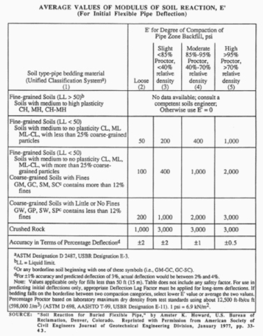
This final parameter required to determine predicted pipe deflection is the Modulus of Soil Reaction. Amster Howard, of the United States Bureau of Reclamation, compiled a table of average E' values for various soil types and densities.
JM Eagle’s SDR 35 PVC sewer pipe has a minimum pipe stiffness of 46 psi. When installed in accordance with the recommendations in our installation guide, this pipe should have a maximum deflection limit for a non-pressure application of 7.5%. Note: this is for ring deflection of the pipe, not axial deflection at the joint.
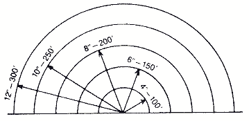
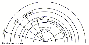
JM Eagle™ does not recommend any deflection at the joint for any of our products. Uni-Bell’s recommendation is that offset at the joint OR uniformly bending the pipe is allowable; however, Uni-Bell does not recommend both on the same length of pipe. Using our 8” SDR 35 sewer pipe as an example, the pipe can be uniformly curved along the barrel of the pipe. There is a minimum radius of curvature, which for this pipe is 200 feet. Per the following calculation, this allows curving across one 20-foot length piece of 5.73°.
Length of arc = p r = (3.14) x (200 ft.) = 628 ft.
Curve per 20’ length / 180° = length of one piece / length of arc
Curve per 20’ length / 180° = 20 ft. / 628 ft.
Therefore: Curve per 20’ length = 5.73°
*Please refer to the Minimum Radii of Curvature Chart below. Click on image to enlarge
The pipe should be assembled above ground, in a straight line, then curved and laid in the trench. All curvature results from the bending of the pipe lengths. There is no deflection at the joint.
*Please refer to the Minimum Radii of Curvature Chart below. Click on image to enlarge
The appropriate conservative "n" value for minimum slope design of PVC sewer pipe is 0.009, as correctly justified by actual test data. The justification of this value is briefly described below.
For many years it has been popular and convenient to use a single "n" value for all pipe materials. However, no data technically support the single "n" value approach, and the most cost-effective sewer designs are precluded by such an over-simplified design criterion. The recognition of "n" value variations among the commonly used sewer pipe materials is long overdue.
No published technical study has ever reported an "n" value as high as 0.013 for a PVC sewer pipeline either in-service or in the laboratory. No published technical study has ever reported PVC sewer pipe as having the same hydraulic characteristics as clay, concrete or asbestos cement under any conditions. The major engineering textbooks dealing with sewer design have yet to address plastic pipe hydraulics. The ASCE and WPCF Manual for Design and Construction of Sanitary and Storm Sewers lists a range of "n" values for "plastic" pipe, i.e., 0.011-0.015, but the authors have not supplied any evidence supporting their recommendations. There is absolutely no scientific basis or technical justification for requiring the use of a 0.013 "n" value when designing PVC sewer pipelines.
The maximum operating temperature for JM Eagle’s PVC pipe is 140 degrees Fahrenheit. For cases where there is a temperature variation, special consideration should be given to the thermal expansion and contraction of the pipe.
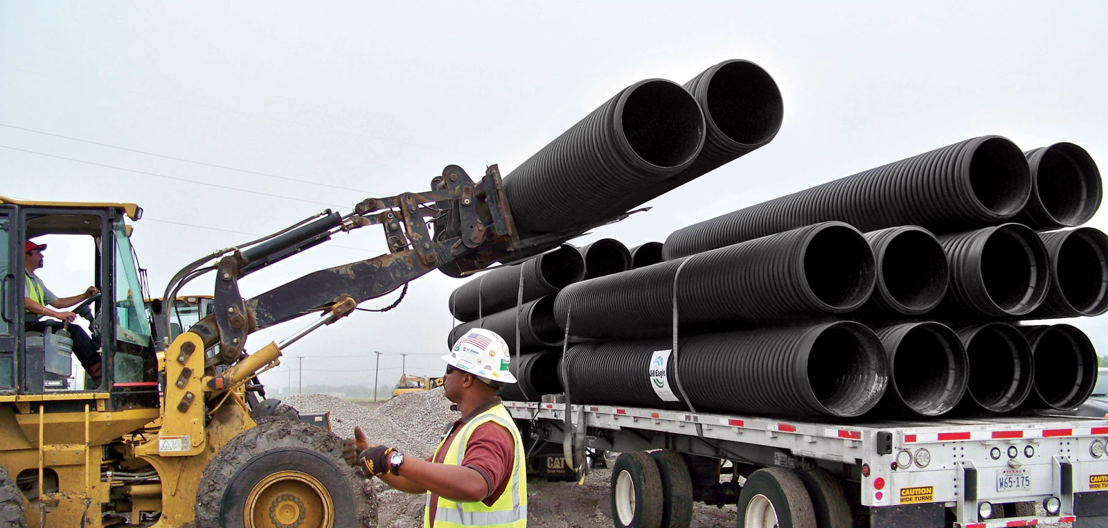
PVC pipe is a light weight yet strong material when compared to many alternatives. A length of PVC pipe will weigh one-fifth of an equivalent size section of cast iron pipe, making it easier to install. This product is easily assembled in solvent-welded or gasketed versions that are both intended to be leak-free, once properly assembled.
JM Eagle™ recommends that our pipe be installed such that the assembly line on the spigot is even with the bell. This also provides greater ease of inspection when verifying proper assembly from the top of the trench.
A joint that is assembled per our recommendations will exhibit a gap, in which the beveled end of the spigot is stopped short of being fully bottomed out in the bell. This gap should be in the allowed tolerance of ½” to 2.5”. Studies have shown that this gap poses no significant effect in terms of head loss or clogging, and is supported by a proven history of fully functional lines. Although bottoming out the spigot into the neck of the bell may yield a joint that appears more attractive when televised, this joint is also more likely to exhibit leakage or breakage due to loss of flexibility or stress from over assembly. By assembling the joint so that the reference mark (or assembly mark) is even with the bell, typical variations in the field can be accommodated. The variations may result from expansion or contraction of the pipe, or the variations may result from deflection at the joint due to soil movement in the trench.
For pipe deflection during installation, please refer to individual installation guide per respective pipe.
JM Eagle’s procedures for installing Rieber and non-Rieber gaskets:
If you have received a combined shipment of JM Eagle™ pipe that contains both Rieber and non-Rieber gaskets, please note the following: non-Rieber and Rieber gaskets adhere to the same standards for the various types of JM Eagle™ pipe. They are both of superior quality and JM Eagle™ will stand behind them with a 100% warranty provided you follow our recommended installation procedures, which are:
- When installing JM Eagle™ pipe with the same type of gaskets, which means Rieber to Rieber pipe or non-Rieber to non-Rieber pipe, you should use the reference marks on the respective type spigot ends.
- When installing two different types of gasketed pipe, JM Eagle™ makes the following recommendations to account for the fact that the Rieber joint has a longer bell and reference mark when compared to the non-Rieber pipe:
- Non-Rieber Spigot to Rieber Gasketed Bell
Follow the non-Rieber pipe reference mark at the spigot end. - Rieber Spigot to Non-Rieber Gasket Bell
Do not insert the pipe all the way to the reference mark on the Rieber pipe spigot end. Instead, use the reference mark that is shown on the non-Rieber pipe. This will require some measurements from JM’s non-Rieber reference mark.
By following the above recommendations, Customers will not experience joint problems such as over-assembly, damaged bells, or cracked bells.
Note: The minimum recommended temperature of PVC pipe during installation should exceed 40 degrees Fahrenheit.
Allowable depth of bury can be calculated based on the allowable deflection as described above. PVC products have been installed successfully at depths of 50 feet or more. The following tables provided as quick reference.
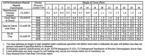
Calculated Deflections of Buried AWWA C900 PVC Pipe (%)

Measured Long-Term Deflections of SDR 35 (PS 46) PVC Pipe (%)
For more details please see: PVC Pipe Trench Construction
Minimum cover is recommended to be one foot from the top of rigid road surfaces or the bottom of flexible road surfaces. At shallow depths of cover (1’ - 3’), Class I or Class II material per ASTM D2321 with a minimum of 95% Proctor density is recommended for pipes ranging from 4”-16”. Angular embedment material shall be no larger than 0.75 inches and rounded rock shall be no larger than 1.50 inches. Also, the maximum particle size should be no greater than 10% of the pipe’s diameter.
For more details please see:
C900 / C905 PVC Pipe Burial Depth Chart
Burial Depth Charts for PVC Stormdrain Pipe Series 14 and 28
PVC Sewer Pipe Burial Depth Chart
Depth of Burial for PVC Pipe
JM Eagle’s pipe bells can be laid either upstream or downstream. There is no significant hydraulic benefit for either direction, and therefore we leave the decision to the discretion of the installer. However, JM Eagle™ recommends that the bell ends point in the direction of work progress to save extra effort. It is easier to insert the spigot into the bell than it is to push the bell over the spigot. This also reduces the risk of rubble being scooped under the gasket. The direction will not adversely affect the performance of the pipe.
For more details please see: Gasketed Pipe Assembly
Lubricate the spigot end of the pipe, using the lubricant supplied. Be sure to cover the entire spigot end circumference WITH PARTICULAR ATTENTION PAID TO THE BEVELED END OF THE SPIGOT. Apply the coating with your hand, a cloth, a pad, a sponge or a glove.
CAUTION: Do not lubricate the bell, especially the gaskets. After spigot end is lubricated, do not allow it to touch the bedding material. Small pieces of stone or soil may stick to the lubricant and may become lodged between the spigot and rubber ring during assembly. This may cause the joint to leak.
Just as PVC pipe with Cast Iron OD’s can be joined to Mechanical Joints that were originally designed for use with Ductile Iron pipe, C900 PVC pipe can be joined directly to Ductile Iron pipe bells, and Ductile Iron pipe can be joined to C900 PVC pipe bells.
JM Eagle™ has two precautions when joining these materials:
- The bevel of the spigot should be made to look like the bevel of the product to which it is being joined. Make a Ductile Iron pipe bevel longer than that which is normally supplied on a Ductile Iron spigot, and make a PVC pipe bevel shorter than that which is normally supplied on a PVC pipe spigot. Use pipe beveled at the factory as a guide.
- The depth of insertion of the assembly should be adjusted to reflect the assembly mark found at the spigot end of the pipe whose bell you are using. Adjust the assembly mark to be shorter on a PVC spigot; and adjust the assembly mark to be longer on a Ductile Iron spigot.
If the joint is over assembled, in other words, the spigot is jammed into the neck of the bell, the flexibility of the joint is lost. Uneven settlement in the trench may cause an over assembled joint to leak – do not assemble beyond the reference mark. Proper assembly calls for insertion of the spigot end into the bell so that it is in contact with the gasket. Keep the pipe lengths in proper alignment. Brace the bell while the spigot end is pushed under the gasket, so that previously completed joints will not be further inserted. Push the spigot into the bell until the assembly mark on the pipe barrel is flush with the end of the bell. Stabbing is not recommended and should be avoided.
If undue resistance to insertion of the spigot end is encountered or the reference mark does not reach the flush position, disassemble the joint and check the position of the gasket. If it is twisted or pushed out of its seat, clean the gasket, bell and spigot end, reseat the gasket properly (using a factory installed gasket as a guide) and repeat the assembly steps. Be sure both lengths are in proper alignment during assembly. If the gasket was not out of position, measure the distance between the reference mark and the spigot end. If necessary, relocate the reference mark if it is out of position.
Lastly, there should be no axial deflection at the joint. Bending the pipe, rather than deflecting the joints, should serve to accomplish small changes in direction.